
Figure: We give diameter of fiber we later glued to the LED and the coupling efficiency. The coupling efficiency is the fraction of light emitted at 30 mA that emerges from the fiber tip.
In series with the LED is a surface-mount resistor that allows us to set the LED forward current once we know the length of the power supply leads. We expect the leads to be 50 mm long in mice and 150 mm long in rats. The resistance of our stretched helical 100-μm wire leads is 10 Ω per 50 mm. The power supply is 5 V and the LED forward voltage is 3.2±0.1 V for currents of order 50 mA. With a 0-Ω resistor and 150 mm leads we will get 32 mA. With a 7-Ω resistor and 50-mm leads we will get 70 mA, assuming the battery can supply the required current to its boost regulator.
We make an 8-mm long fiber of higher-index glass. The fiber has a 2-mm taper at one end a flat on the other. Its diameter is 440 μm. We its base onto the center of the LED. We squash down the bond wire, but there remains a gap of roughly 100 μm between the fiber base and the LED surface. Our calculated coupling efficiency for a fiber with outer diameter 440-μm and numerical aperture 0.86 is 47%. We expect to lose 2% of this light in the yellow glass of the fiber, which will reduce our coupling efficiency to 46%. Our calculation assumes, however, that the LED and fiber surfaces are touching.
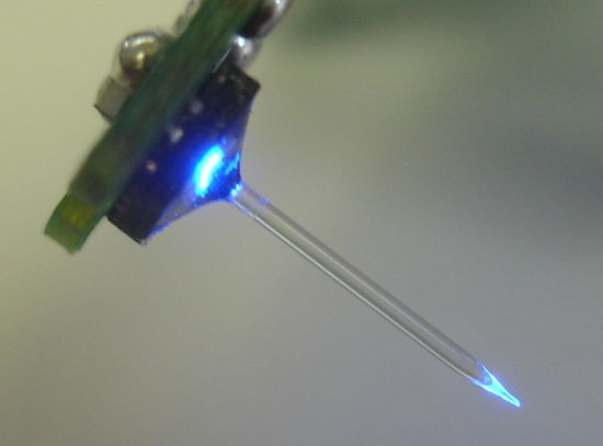
Figure: Higher-Index Taper Glued to Blue LED. Assembly number A3024HFB, serial number 2.10.
We mask the base of the fiber with tape and pass 30 mA through the LED. We measure the photocurrent in our 10 mm × 10 mm photodiode at range 20 mm for the fiber tip. We vary the angle, θ, between the axis of the fiber and the line joining the tip to the center of the photodiode. We orient the photodiode so its surface is always perpendicular to this line. For θ = 90° we go around the fiber in a horizontal plane in 45° steps. The light intensity varies from 50-110 μW/cm2, with an average of 80 μW/cm2. We move the photodiode in a vertical plane and vary θ from 90° to −90°. We obtain the following plot of intensity versus angle.

Figure: Intensity versus Off-Axis Angle for Fiber Tip. The fiber base is masked with black tape. We move our 1 cm2 photodiode around in a vertical plane at range 2 cm. Assembly number A3024HFB, serial number 2.10.
By integrating this curve for the hemisphere above the taper, we obtain a crude estimate of 9 mW for the total emitted power. To obtain a better estimate, we place our 1 cm2 photodiode in five positions on four sides and above the tip of the fiber, at range 5 mm, so as to make a cube that receives all emitted power. We add the photocurrents thus obtained, after subtracting for background light, and arrive at a total of 1.76 mA, which suggests a total output power of 9.8 mW at 30 mA forward current. Given that this LED emitted 26.7 mW at 30 mA, our coupling efficiency to the tip is 37%. We increase the LED current to 50 mW and optical power output increases by 45% to approximately 14.3 mW. For the first time, we have a taper that emits roughly 10 mW with forward current 30 mA. If we increase the LED current to 70 mA, which will be possible with a rat-sized lithium-ion battery, this fiber tip will emit 19 mW. This fiber's coupling efficiency is 37%, compared to a theoretical maximum of 46%.
To complete the head fixture, we need a 9-mm silica guide cannula. Our existing guides are 7-mm long. Our plan is to glue the tip of the guid to the base of the taper, and measuring with the existing taper, the guide cannula length below the plastic thread must be 9 mm.
UPDATE: [24-DEC-13] In No2.2, we use the offset placement of the fiber shown here, which allows us to press the fiber base onto the surface of the LED. We get 5.7 mW for 30 mA, or 22% coupling efficiency.
UPDATE: [23-JAN-14] By squeezing the fiber clamp with our fingers, we force the fiber base closer to the LED surface. This appears to increase our coupling efficiency from 37% to 38%.
UPDATE: [24-JAN-14] We take out head fixture A3024HFB No2.6 and measure its power output with 30 mA. We mask the LED with aluminum foil. With angled photodiode we get 10.4 mW total power output. With the fiber perpendicular to the photodiode and the tip touching the photodiode, we get 1.3 mA of photocurrent, or 7.3 mW incident light. Given that the photodiode extends for 5 mm from the tip, and the light emission takes place along a 1-mm length, everything emitted within ±84° of the fiber axis is incident upon the photodiode. The missing 3 mW must be emitted at an angle greater than ±84°.
No comments:
Post a Comment